Nächste Seite: Webcam und Forum Aufwärts: Übungen Vorherige Seite: i2c, Timer-interrupt, Interrupts
 0 0 0 0 0    0
 1 0 0 0 1    0
 2 0 0 1 0    1
 3 0 0 1 1    1
 4 0 1 0 0    0
 5 0 1 0 1    0
 6 0 1 1 0    1
 7 0 1 1 1    0
 8 1 0 0 0    0
 9 1 0 0 1    1
10 1 0 1 0    1
11 1 0 1 1    0
12 1 1 0 0    0
13 1 1 0 1    1
14 1 1 1 0    1
15 1 1 1 1    0


 2 0 0 1 0    1
 3 0 0 1 1    1
 6 0 1 1 0    1
 9 1 0 0 1    1
10 1 0 1 0    1
13 1 1 0 1    1
14 1 1 1 0    1


Gruppe 1:
 2 0 0 1 0    1
Gruppe 2:
 3 0 0 1 1    1
 6 0 1 1 0    1
 9 1 0 0 1    1
10 1 0 1 0    1
Gruppe 3:
13 1 1 0 1    1
14 1 1 1 0    1

2:3         0   0   1   -
2:6         0   -   1   0
2:10        -   0   1   0
6:14        -   1   1   0
9:13        1   -   0   1
10:14       1   -   1   0


2:3         0   0   1   -
9:13        1   -   0   1
10:14       1   -   1   0
2:6         0   -   1   0
2:10        -   0   1   0
6:14        -   1   1   0


2:3         0   0   1   -

Gruppe 1:
2:6         0   -   1   0
Gruppe 2:
9:13        1   -   0   1
10:14       1   -   1   0

Gruppe 1:
2:10        -   0   1   0
Gruppe 2:
6:14        -   1   1   0


2:3             0   0   1   -

Gruppe 1:
2:6         0   -   1   0
Gruppe 2:
9:13            1   -   0   1
10:14       1   -   1   0

2:6:10:14       -   -   1   0

Gruppe 1:
2:10        -   0   1   0
Gruppe 2:
6:14        -   1   1   0

2:10:6:14       -   -   1   0


2:3             0   0   1   -
9:13            1   -   0   1
2:6:10:14       -   -   1   0
2:10:6:14       -   -   1   0


2:3             0   0   1   -
9:13            1   -   0   1
2:6:10:14       -   -   1   0

                2   3   6   9   10  13  14
2:3             +   +
9:13                        +       +
2:6:10:14       +       +       +       +

2:3             0   0   1   -
9:13            1   -   0   1
2:6:10:14       -   -   1   0

Disjunktive Normalform:
    y   <=  (not x3 and not x2 and x1) or
            (x3 and not x1 and x0) or
            (x1 and not x0);
Konjunktive:
    y   <=  not (
                    (x3 or x2 or not x1) and
                    (not x3 or x1 or not x0) and
                    (not x1 or x0)
                );

library ieee;
use ieee.std_logic_1164.all;

entity quine20241025 is
port (
    x3, x2, x1, x0: in std_logic;
    y: out std_logic
);
end;

architecture behaviour of quine20241025 is
begin
    y   <=  (not x3 and not x2 and x1) or
            (x3 and not x1 and x0) or
            (x1 and not x0);
end;

library ieee;
use ieee.std_logic_1164.all;

entity quine20241025_testbench is
port (
    y: inout std_logic
);
end;

architecture behaviour of quine20241025_testbench is
    component quine20241025 is
    port (
        x3, x2, x1, x0: in std_logic;
        y: out std_logic
    );
    end component;
    signal x3, x2, x1, x0: std_logic;
begin
    q: quine20241025 PORT MAP (x3=>x3, x2=>x2, x1=>x1, x0=>x0, y=>y);
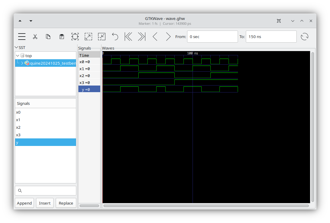
VHDL:
library ieee;
use ieee.std_logic_1164.all;

entity quine20241025 is
port (
    x3, x2, x1, x0: in std_logic;
    y: out std_logic
);
end;

architecture behaviour of quine20241025 is
begin
    y   <=  (not x3 and not x2 and x1) or
            (x3 and not x1 and x0) or
            (x1 and not x0);
end;

library ieee;
use ieee.std_logic_1164.all;

entity quine20241025_testbench is
port (
    y: inout std_logic
);
end;

architecture behaviour of quine20241025_testbench is
    component quine20241025 is
    port (
        x3, x2, x1, x0: in std_logic;
        y: out std_logic
    );
    end component;
    signal x3, x2, x1, x0: std_logic;
begin
    q: quine20241025 PORT MAP (x3=>x3, x2=>x2, x1=>x1, x0=>x0, y=>y);
    x0 <= '0' after 0 ns, '1' after 10 ns, '0' after 20 ns, '1' after 30 ns, '0' after 40 ns, '1' after 50 ns, '0' after 60 ns, '1' after 70 ns, '0' after 80 ns, '1' after 90 ns, '0' after 100 ns, '1' after 110 ns, '0' after 120 ns, '1' after 130 ns, '0' after 140 ns, '1' after 150 ns;

    x1 <= '0' after 0 ns, '0' after 10 ns, '1' after 20 ns, '1' after 30 ns, '0' after 40 ns, '0' after 50 ns, '1' after 60 ns, '1' after 70 ns, '0' after 80 ns, '0' after 90 ns, '1' after 100 ns, '1' after 110 ns, '0' after 120 ns, '0' after 130 ns, '1' after 140 ns, '1' after 150 ns;

    x2 <= '0' after 0 ns, '0' after 10 ns, '0' after 20 ns, '0' after 30 ns, '1' after 40 ns, '1' after 50 ns, '1' after 60 ns, '1' after 70 ns, '0' after 80 ns, '0' after 90 ns, '0' after 100 ns, '0' after 110 ns, '1' after 120 ns, '1' after 130 ns, '1' after 140 ns, '1' after 150 ns;

    x3 <= '0' after 0 ns, '0' after 10 ns, '0' after 20 ns, '0' after 30 ns, '0' after 40 ns, '0' after 50 ns, '0' after 60 ns, '0' after 70 ns, '1' after 80 ns, '1' after 90 ns, '1' after 100 ns, '1' after 110 ns, '1' after 120 ns, '1' after 130 ns, '1' after 140 ns, '1' after 150 ns;
end;
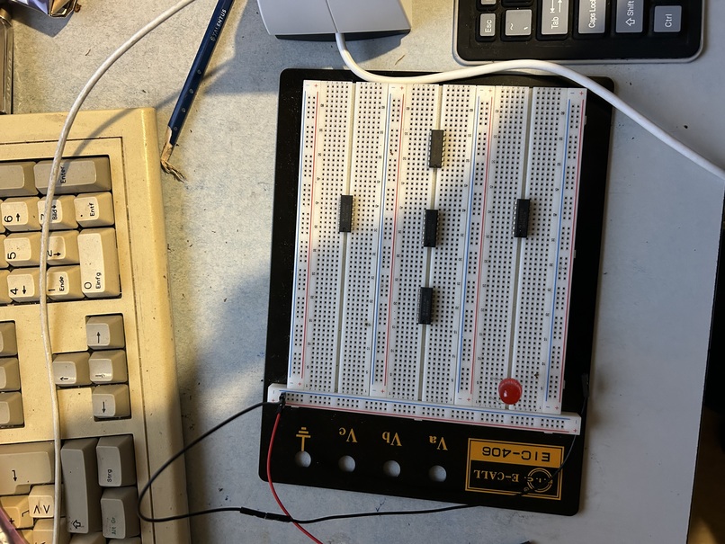
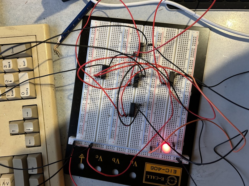
; hier ist ja der alte Quelltext, zum hochzaehlen der Eingangsvariablen, er erzeugt, siehe Video, ich werde die warteschleife jetzt durch ein anstaendiges Timer Interrupt ersetzen, vorher muss ich gucken, wie man den Atmega8 auf dem STK 500 ueber avrdude auf 4 MHz taktet
.include "m8def.inc"

ldi r16, HIGH (RAMEND)
out SPH, r16
ldi r16, LOW (RAMEND)
out SPL, r16

ldi r16, 0xff
out DDRD, r16
out DDRB, r16

ldi r16, 0x01
loop1:
mov r17, r16
com r17
out PORTB, r17
out PORTD, r16
rcall sleep
inc r16
cpi r16, 0b00010000
brne loop1
ldi r16, 0x00
rjmp loop1

sleep:
push r16
push r17
push r18
ldi r16, 0xff
sleep_loop1:
dec r16
ldi r17, 0xff
sleep_loop2:
dec r17
ldi r18, 0x08
sleep_loop3:
dec r18
cpi r18, 0x01
brne sleep_loop3
cpi r17, 0x01
brne sleep_loop2
cpi r16, 0x01
brne sleep_loop1
pop r18
pop r17
pop r16
ret
ich habe herausgefunden, ich muss nichts aendern, die CPU laeuft bereits, mit 3,686 MHz, selbst, wenn sie es nicht tun wuerde, ich muesste es bei den Timer Interrupts richtig handhaben. hier die Parameter fuer avrdude um den Fuses auszu lesen
root@work:/home/david# avrdude -c stk500 -p atmega8 -P /dev/ttyS3 -n -vHabe ich hier gefunden https://www.mikrocontroller.net/articles/AVR_Fuses muss man auch auswendig lernen. Es ist nicht nur notwendig heraus zu finden, wie ich die Fuses aendere, sondern wie sie ueberhaupt sind, Ausgabe:
avrdude: Version 7.1
         Copyright the AVRDUDE authors;
         see https://github.com/avrdudes/avrdude/blob/main/AUTHORS

         System wide configuration file is /etc/avrdude.conf
         User configuration file is /root/.avrduderc
         User configuration file does not exist or is not a regular file, skipping

         Using Port                    : /dev/ttyS3
         Using Programmer              : stk500
         AVR Part                      : ATmega8
         Chip Erase delay              : 10000 us
         PAGEL                         : PD7
         BS2                           : PC2
         RESET disposition             : possible i/o
         RETRY pulse                   : SCK
         Serial program mode           : yes
         Parallel program mode         : yes
         Timeout                       : 200
         StabDelay                     : 100
         CmdexeDelay                   : 25
         SyncLoops                     : 32
         PollIndex                     : 3
         PollValue                     : 0x53
         Memory Detail                 :

                                           Block Poll               Page                       Polled
           Memory Type Alias    Mode Delay Size  Indx Paged  Size   Size #Pages MinW  MaxW   ReadBack
           ----------- -------- ---- ----- ----- ---- ------ ------ ---- ------ ----- ----- ---------
           eeprom                  4    20   128    0 no        512    4      0  9000  9000 0xff 0xff
           flash                  33    10    64    0 yes      8192   64    128  4500  4500 0xff 0x00
           lfuse                   0     0     0    0 no          1    1      0  2000  2000 0x00 0x00
           hfuse                   0     0     0    0 no          1    1      0  2000  2000 0x00 0x00
           lock                    0     0     0    0 no          1    1      0  2000  2000 0x00 0x00
           signature               0     0     0    0 no          3    1      0     0     0 0x00 0x00
           calibration             0     0     0    0 no          4    1      0     0     0 0x00 0x00

         Programmer Type : STK500V2
         Description     : Atmel STK500
         Programmer Model: STK500
         Hardware Version: 2
         Firmware Version Controller : 2.10
         Topcard         : Unknown
         Vtarget         : 4.6 V
         SCK period      : 35.3 us
         Varef           : 4.5 V
         Oscillator      : 3.686 MHz

avrdude: AVR device initialized and ready to accept instructions
avrdude: device signature = 0x1e9307 (probably m8)

avrdude done.  Thank you.
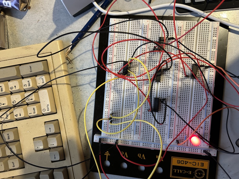
funktioniert bestens und jetzt sieht man, es stimmt mit den Sekunden
.include "m8def.inc"

.def temp = r16
.def leds = r17
.def seconds = r18

.org 0x0000
        rjmp    start
.org OVF0addr
        rjmp    timer0_overflow

start:
        ldi     temp, HIGH(RAMEND)
        out     SPH, temp
        ldi     temp, LOW(RAMEND)
        out     SPL, temp
        ldi     temp, 0xFF
        out     DDRB, temp
        out     DDRD, temp
        ldi     leds, 0x00
        ldi     seconds, 0x00
        ldi     temp, (1<<CS02) | (1<<CS00)
        out     TCCR0, temp
        ldi     temp, (1<<TOIE0)
        out     TIMSK, temp
        sei

loop:   rjmp    loop

timer0_overflow:
        cpi     seconds, 0x04
        brlt    no_led_toggle
        cpi     leds, 0b00000111
        brlt    goon
        ldi     leds, 0x00
        rjmp    no_inc
goon:
        inc     leds
no_inc:
        com     leds
        out     PORTB, leds
        com     leds
        out     PORTD, leds
        ldi     seconds, 0x00
no_led_toggle:
        inc     seconds

        reti
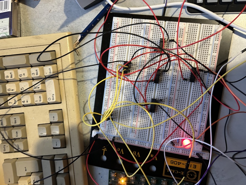
so ist besser
.include "m8def.inc"

.def temp = r16
.def leds = r17
.def seconds = r18

.org 0x0000
        rjmp    start
.org OVF0addr
        rjmp    timer0_overflow

start:
        ldi     temp, HIGH(RAMEND)
        out     SPH, temp
        ldi     temp, LOW(RAMEND)
        out     SPL, temp
        ldi     temp, 0xFF
        out     DDRB, temp
        out     DDRD, temp
        ldi     leds, 0x00
        ldi     seconds, 0x00
        ldi     temp, (1<<CS02) | (1<<CS00)
        out     TCCR0, temp
        ldi     temp, (1<<TOIE0)
        out     TIMSK, temp
        sei

loop:   rjmp    loop

timer0_overflow:
        cpi     seconds, 0x04
        brlt    no_led_toggle
        cpi     leds, 0b00000111
        brlt    goon
        ldi     leds, 0x00
        rjmp    no_inc
goon:
        inc     leds
no_inc:
        com     leds
        out     PORTB, leds
        com     leds
        out     PORTD, leds
        ldi     seconds, 0x00
no_led_toggle:
        inc     seconds

        reti
x2	x1	x0	y
0	0	0	0
0	0	1	1
0	1	0	0
0	1	1	1
1	0	0	1
1	0	1	0
1	1	0	0
1	1	1	0
und
0 0 0 0 0    0
 1 0 0 0 1    0
 2 0 0 1 0    1
 3 0 0 1 1    1
 4 0 1 0 0    0
 5 0 1 0 1    0
 6 0 1 1 0    1
 7 0 1 1 1    0
 8 1 0 0 0    0
 9 1 0 0 1    1
10 1 0 1 0    1
11 1 0 1 1    0
12 1 1 0 0    0
13 1 1 0 1    1
14 1 1 1 0    1
15 1 1 1 1    0

    y   <=  (not x3 and not x2 and x1) or
            (x3 and not x1 and x0) or
            (x1 and not x0);
und
 0 0 0 0 0    0
 1 0 0 0 1    0
 2 0 0 1 0    1
 3 0 0 1 1    1
 4 0 1 0 0    1
 5 0 1 0 1    0
 6 0 1 1 0    1
 7 0 1 1 1    1
 8 1 0 0 0    1
 9 1 0 0 1    1
10 1 0 1 0    0
11 1 0 1 1    1
12 1 1 0 0    0
13 1 1 0 1    0
14 1 1 1 0    1
15 1 1 1 1    1

        y   <=  (not x3 and x1) or
            (x3 and not x2 and not x1) or
            (x2 and x1) or
            (not x3 and x2 and not x0) or
            (x1 and x0);
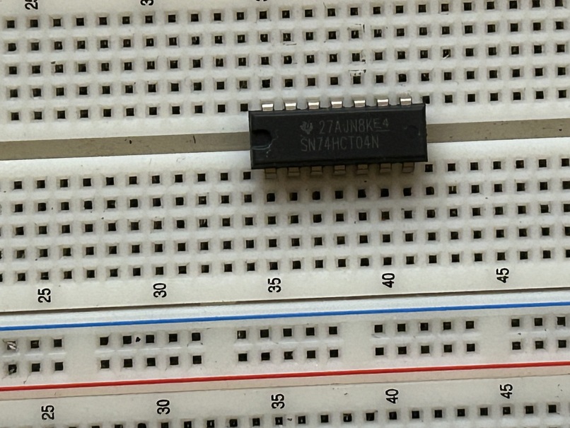
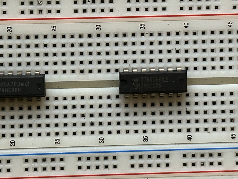
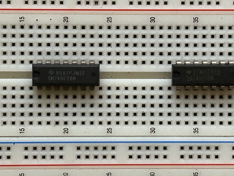
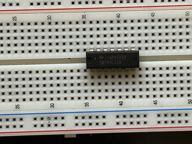
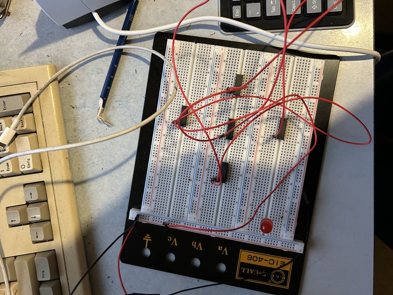
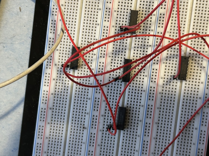
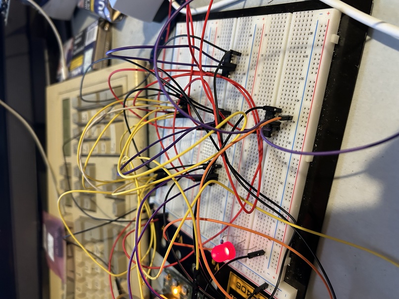
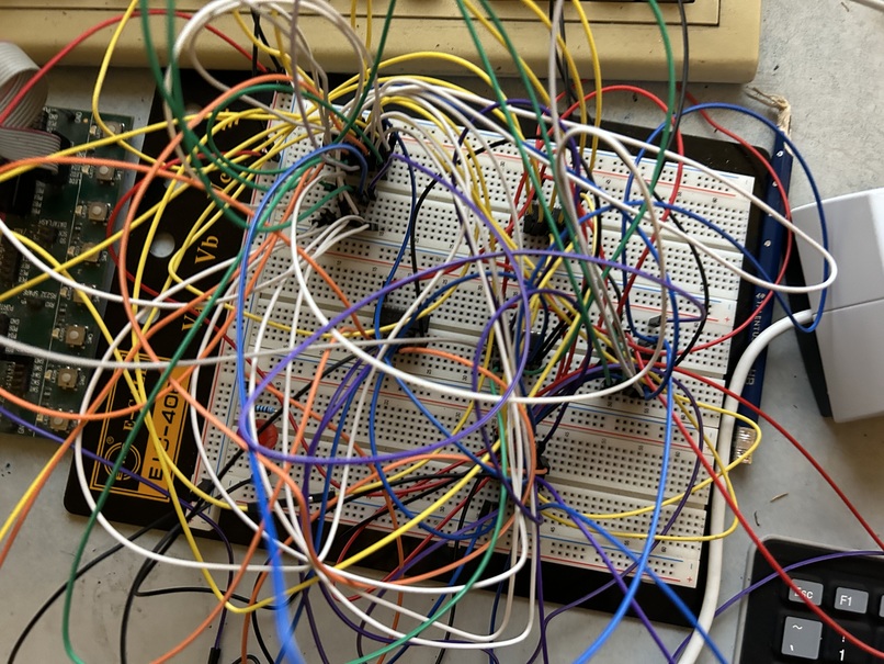
ein kleiner fehler ist drin, dafuer ist es diesmal ein OR mit 5 eingaengen, ich will gleich was zu essen kaufen und habe schon zwei schaltungen gebaut.
ich werde ihn nicht nachtraeglich suchen